Yes, we do shaft modifications ranging from a wide variety of options: multiple flat options, helical cut shaft, tapped center holes, press fit gear and pulley shafts, cross drilled shafts, extended or shortened shafts, slotted shaft options, and more.


Servo-Drive can do custom housings for your stepper motor, whether it's going to be in a Clean Room Environment, or if you need a stainless steel finish, anodized finish, or specific assembly integration with your system.
The lube on the bearings and the adhesive used has the biggest effect on the operating range of step motors. Lin Engineering can customize our step motors to fit the desired operating specifications. High temp motors, for example, can have the below added modifications:
1.High temp magnet wires
2.High temp bearing lube
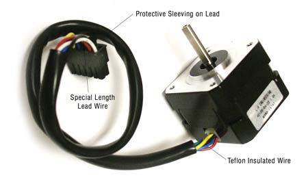
3.High temp lead wires (or teflon coated lead wires)
Please contact Servo-Drive for further details.
Our 4218 and 5718 series motors can be qualified with IP65 ratings. The IP65 Series of motors are totally protected against dust as well as guaranteed to withstand low pressure jets of water sprayed from all directions from a distance of 3 meters. These jets of water can carry pressure of up to 30 kPa from all directions at a rate of 12.5 l/min for the duration of 3 minutes. In addition to being protected from environmental factors, the coating on our IP65 Series motors is also FDA approved. The "6" is dust protection, the “5” is low pressure jets of water.
Our 5718 series motors can also be qualified with IPX7 ratings. The IPX7 series of motors are completely protected against dust; they are also made to withstand immersion into liquids in depths of 15cm to 1m for time periods of up to 30 minutes. In addition to being protected from environmental factors, the coating on our IPX7 Series motors is also FDA approved.
We design and manufacture stepper motors with any customization, whether the quantity is big or small. Other modifications include lead wire modifications and sub-assembly work such as: extended or shorter leads, custom color code, 8-wire configuration, protective sleeving, shrink tubing and installation of pins and connectors.

Our 4218 and 5718 series motors can be qualified with IP65 ratings. The IP65 Series of motors are totally protected against dust as well as guaranteed to withstand low pressure jets of water sprayed from all directions from a distance of 3 meters. These jets of water can carry pressure of up to 30 kPa from all directions at a rate of 12.5 l/min for the duration of 3 minutes. In addition to being protected from environmental factors, the coating on our IP65 Series motors is also FDA approved. The "6" is dust protection, the “5” is low pressure jets of water.
Our 5718 series motors can also be qualified with IPX7 ratings. The IPX7 series of motors are completely protected against dust; they are also made to withstand immersion into liquids in depths of 15cm to 1m for time periods of up to 30 minutes. In addition to being protected from environmental factors, the coating on our IPX7 Series motors is also FDA approved.
We will mainly discuss bipolar hybrid step motors, since this is what
the industry standard is and Lin Engineering manufactures hybrid step
motors (both unipolar and bipolar)
Let’s first start with some definitions. A step motor is comprised of a few components: a stainless steel shaft that runs through the whole motor assembly, a rotor which is comprised of a magnet in the middle of the rotor sections, bearings on the front and rear side of the motor, a steel stator that surrounds the rotor, and magnet wires that are wound around the poles of the stator. Both the rotor and stator contain teeth.
how_does_it_work_stepmotor_cutout_labeled.jpg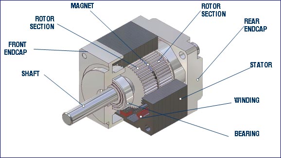
Step motors are used in applications that require precise movements and need to hold in place without losing its position. Different increments of current are applied to the windings in order to make the motor step. When the motor stalls, it will never burn up or break. You can also give instructions to the motor to microstep, or step in tiny increments as small as 0.0035°, so if precise movements is what you need, you’ve come to the right place.
Conventional AC and DC motors operate on a continuously applied input voltage and most often produce a continuous (steady state) rotary motion. For example, the fan in your home is plugged into the wall and receives a constant AC voltage to produce three different constant speeds of low, medium, and high. Most commercial type motors are single phase, equipped with two lead wires, the third lead as a grounding lead. Current flows from one lead wire into the motor and return through the other lead wire.
Unlike these motors, a step motor (also called a stepping motor or a stepper) will not produce continuous motion from a continuous input voltage. It will stay at a particular position as long as the power is “on”. An electrical phase change is necessary to make a step motor move. This means that no single-phase step motor can exist.
In a typical step motor, the windings are considered as two long wires that contain a resistance and an inductance with switches for allowing current to flow or to stop the flow in order to make the motors move a step.
Turning one phase on will hold the rotor in one position (called a detent position). Turning off this phase and turning on the second phase will move the rotor to rest at another detent position. This “on and off” current flow is called a pulse. One pulse into the motor causes the rotor to increment (move) one precise angle. This movement is repeated with each input pulse in order to create continuous rotational motion.
When properly applied and controlled, the number of output steps is always equal to the number of input pulses.
The rotor can be held at any one particular position by continuing to send current into one of the phases. In doing so, the motor has holding torque, which can be used to hold a device in place. Furthermore, if the motor is rotating with a constant input of step pulses and an object blocks the motor from rotating, or stalls the motor, it will not burn up. The pulses are still continually going in, turning on and off. Power does not continue to build up, but rather it continues to change constantly. Unlike the fan, for example, this type of motor won’t burn. But if you were to place your pencil in between the blades of a fan and purposely stall it, it will continue to draw more AC voltage until it eventually burns.
The name “Hybrid” comes from the fact that these types of steppers are a hybrid between a “variable reluctance” motor and a “PM” motor.
A variable reluctance uses concepts of a magnetic circuit with a gap which will produce a force to close the gap. The ‘reluctance’ of the magnetic circuit (its resistance to the magnetic flux) can be varied as the position of the rotating core is changed.
A PM motor, or a Permanent Magnet motor, uses the concept of North and South poles on a magnet in order to produce more of a magnetic flux path. The flux path dictates which direction the motor will rotate.
The Hybrid stepper has windings around the steel poles of the stator. There is a magnet placed in between the rotor sections and an airgap is formed between the rotor and stator. The ball bearings are the only contact in rotation.
If we were to take a step motor sitting on a bench with the shaft pointing upwards, and cut it long ways (make a cut through the motor, perpendicular to the ground) and unravel it, this is what you would see:
When the A Phase is turned on, the flux path is shown in pink. Current flows through the A phase, where the windings are wound on every 4th pole in this case. Since the rotor contains a magnet, the flux path will flow from North to South, forcing the teeth of the rotor to line up with the stator tooth that is energized at that time.
By turning off the A Phase and energizing the B Phase, the motor is forced to line up with the B-Phase. Each transition of currents is what forces the motor to step in tiny increments. And note that after four changes, the rotor has moved one full tooth length.
Most step motor manufacturers have 0.45°, 0.9° and 1.8° steppers. Here is where it stems from:
There are 360° in one revolution. We also saw that it required four mechanical phases to move one tooth. In other words, the number of full steps required to repeat the same mechanical line up between stator tooth and rotor tooth.
In a 1.8° stepper (meaning each step moves the motor 1.8°), there are 50 teeth on the rotor. Therefore in 1 revolution or 360°, 50 teeth times 4 mechanical phases, or 200, is divided by 360 for us to come up with 1.8° per step.
NT = # of teeth
S = Full step angle
NP = # of mechanical phases
S = 360° / (NP X NT)
S = 360° / (50 x 4) = 1.8° per full step
OR
NT = 360° / (S x NP)
NT = 360° / (1.8 x 4) = 50 teeth
Therefore, only certain step angles exist due to the nature of the design. For reference, a 5-Phase bipolar step motor has 10 mechanical phases. But a 3-Phase Unipolar step motor has 3 mechanical phases.
Bi = two
Uni = one
What does it all mean when it comes to steppers?
A bipolar step motor is one that contains four lead wires, labeled as the A phases and the B phases. Within the A phase there is: A and A Bar. Within the B phase there is: B and B Bar.
When a bipolar motor is wound, you start with one wire, let’s say “A”. It is wound around every other stator pole until it finishes, and is pulled out to be labeled as “A Bar”. This means, the A and A Bar is one long magnet wire. The same happens with the B and B Bar, where this wire is then wound around the remaining poles.
When one electrical pulse enters the A wire it will flow through the windings and flow out of A Bar.
A bipolar motor can have current flow in both directions: both through A and out A Bar, and through A Bar and out A. Therefore, Bi = two, for two directional current flow.
This depicts the windings of a step motor, where the circle is the rotor, and the windings are shown so that you see two distinct phases: A and B. Current can flow in either direction.
You can now guess that a Unipolar only allows the flow of current through one direction. Yes, unipolar motors always have current flowing in one way and out one way. But furthermore, a unipolar contains 6 wires. Where did the extra two wires come from? In the bipolar explanation, we saw that the A and A Bar was one long wire. In a unipolar motor, they also start with the A wire, but half way through the winding process, an extra wire is pulled out of the motor. The winding continues and finishes with the A Bar, but now, on each phase, there are two more wires. These are called the common wires, because they are common to A and A Bar for example. The extra wire in the B Phase is common among the B and B Phase.
Current always flows in one of the main phases and out the common wire. The common wire is also called common ground, as the name implies, it is connected to ground, therefore forcing current to always flow from + to GND. In order to get a unipolar motor to step one by one, the switching of current flow occurs similar to the bipolar motors, but it’s switching off between half of the A phase and half of the B Phase. Notice when the current flows in a unipolar motor, only half the full phase is being used. The correct terminology is to say that one coil is energized at once. A bipolar motor energizes two coils at once.
So, we have now learned there are two reasons why we call these motors bipolar and unipolar:
| Unipolar | Bipolar |
| Uni = one | Bi = two |
| One direction of current flow | Two directions of current flow |
| One coil is energized at a time | Two coils are energized at a time |
A unipolar motor can in fact be re-wired to be used like a bipolar motor. There are two options. A series connection would mean to combine each section in series. In other words, if we ignore the center taps (the common wires) and simply use A, A Bar, B and B Bar, then it now looks like the Bipolar winding we’ve talked about above.
Another connection is called the Half-Coil connection. It is used when we want to simulate the function of the unipolar motor, but we only have a bipolar driver and system. We’d simply ignore the A Bar and the B Bar wires. Therefore, we’re back to four wires again, and we are only using half of the coils.
Every step motor needs a stepper driver. There are several types of drivers out there. A unipolar driver is required to rotate a unipolar motor. And a bipolar driver is required to make a bipolar motor rotate.
In order to turn on and off the currents going from phase to phase, transistors must be used to make this happen.
|
|
|
|
This is what a transistor looks like. The base controls the amount of current flowing from Collector to Emitter. |
Think of it as a switch, where the Base controls current flow. |
Almost all bipolar drivers use an H-bridge technology where four transistors are used for current to flow through the A and B phases.
|
|
|
Basic H-Bridge circuit |
|
|
|
Current flowing through “A” |
|
|
|
Current flowing through “B” |
The most common bipolar driver is the chopper drive with PWM technology (Pulse Width Modulation).
A chopper drive will “chop” or turn on and off the incoming voltage (DC volts) in order to limit the current to a set and known value. This is also known as a current-controlled system.
The driver will allow you to set the current to a known value. As 24VDC is sent to the drive, for example, it will stay on until current has reached it’s designated rated current. Then the 24VDC will be turn on and off.
When you see that your motor has a voltage rating, it’s simply due to V = I*R Ohm’s Law. Since motors have a resistance rating from the winding, it also has a current rating in order not to exceed a total Power (I^2*R) requirement. Therefore, there is also a voltage rating. It does not mean you cannot exceed the voltage rating. This is because of the chopper drive technology. The more important factor is the current rating. One must not exceed the motor’s rated current that is set on the drive.
Any step motor can be microstepped. This is because microstepping is a function of the driver. A driver determines how much or how little current will flow to the motor windings. A specific ratio of currents for the A & B phases will force the motor to step in areas where it naturally wouldn’t step.
For example, if you have a 1.8° step motor, each step it takes will move 1.8°. It would take 200 steps to make one complete revolution (360° / 1.8° = 200 steps/rev).
If you set the driver to half step, each step is now 0.9°. (1.8° / 2 = 0.9°) Therefore, it now requires 400 steps to make one complete revolution.
If you set the driver to quarter step, or 4x microstepping, each step is now 0.45°. (1.8° / 4 = 0.45°). It now requires 800 steps to make one complete revolution.
The maximum step resolution that is standard to the industry is 256x microstepping. One step is 0.007° with a 1.8° stepper. If you use a 0.9° stepper and set the drive to 256x microstepping, each step will then be 0.0035°.
1. The application requires the motor to stop at very fine increments or very specific degrees that can’t be done through full stepping a motor.
2. The application requires smooth motion, and by moving at tiny increments, oscillations made per step is very subtle and small.
3. The application requires less noise. Smaller oscillations per step will not allow the unit to resonate and create noise.
Above shows the current waveform of the A Phase during full stepping. The A Phase will be on for two steps, then off for two steps. It continues along this pattern forever.
The B Phase looks the same, but the timing at which it is on and off are offset.
Below is what the half-stepping waveform looks like. By giving the A and B phases various currents, it forces the motor to step in between the natural full step positions.
Since step motors contain a magnet inside the rotor, and copper is wound around steel poles, magnetic fields are created in order to force the motor to step, and even hold in that position forever.
Think of the magnetic flux as a rubberband, holding the teeth of the stator and rotor in one position since the rubberband is tighter in those areas.
When A is “ON” and B is “OFF”, the rotor and stator are stable in one position. The second A is turned “OFF” and B is turned “ON”, the flux path is stretched, shown in the middle image above. Like a rubber band, it likes the path of least resistance, and therefore is now stable at the B position. This is how one step is made.
At position #1, notice in the waveform, the blue waveform, or the A Phase, is receiving all the current. The green waveform, or the B Phase, has zero current. The image above depicts this situation, where the parts are stable at A.
To force the motor to step just ¼ of the way from A to B at position 2, A must receive twice the amount of current as B. The waveforms clearly show this as well.
To force the motor to step right in the middle of A and B, both phases must receive equal amounts of currents, and it holds true at position 3 in the waveforms.
Step accuracy is the primary character of a step motor. Without step accuracy, the motor is useless. Based on motor manufacturing capability, step accuracy is rated at +/- 5% of the full step. That means a 1.8-degree motor would have step error of +/- 5.4 arc minutes, while 0.9-degree motor would have step error at +/- 2.7 arc minutes. this is because the motor step accuracy is determined by the torque stiffness, and the torque stiffness is determined by maximum holding torque and the number of rotor teeth.
Motor torque function: T( Phi ) = To*Sin(N Phi)
Torque stiffness: dT( Phi )/d Phi = N*To*Cos(N* Phi)
(where To=maximum holding torque, N=number of rotor teeth, =rotor displacement)
A 1.8-degree motor has a 50-tooth rotor and 0.9-degree motor has a 100-tooth rotor. With the same manufacturing capability, a 0.9-degree motor will have twice the step accuracy of a 1.8-degree motor.
Unipolar - A unipolar driver's output current direction cannot be changed. There are two sets of the coils for each phase in a motor. Only one set of the coils can be energized at a time. Each coil represents one phase. Therefore, only 50% of the winding is utilized in the unipolar drive. The number of mechanical phases equals the number of electrical phases.
Due to the fact unipolar drivers only use 50% of the windings, the performance ranges from low to moderate. The benefit of this is that it doesn't generate too much heat.
Bipolar - A bipolar driver's output current direction can be changed. 100% of the winding is utilized in the bipolar drive. That means the two sets of the coils in each phase can be connected either in series or in parallel to become one set of a coil. Current direction changed from the driver creates another mechanical phase.
The number of mechanical phases is always twice the number of electrical phases. Bipolar drivers provide 40% more holding torque than unipolar drivers, but typically run at higher temperatures. For that reason, proper heat dissipation important with bipolar drivers.
Holding torque is the maximum restoring torque developed by the rotor when one or more phases of the motor are energized. The dynamic torque is called running torque or pullout torque. It varies at different speed by different driver technologies and power input. As a rule of thumb, the maximum dynamic torque is about 70% of the holding torque.
Rated current is what the motor is rated at. Peak current refers to the amount of current the driver outputs. When using a driver that only does half or full stepping, the rated current is the same as the Peak current. (Rated current = Peak Current).
When using a driver that is capable of doing microstepping (microstepping = 1/4 stepping or more), the definition of Peak current becomes 1.4 times the rated current. Microstepping drivers are made differently in order to maximize it's ability to drive the step motor. Therefore, step motors can handle up to it's rated current, multiplied by 1.4. (Peak Current = 1.4 x Rated Current). This will not damage the motor because the power output is more or less the same.
Non-microstepping drivers: Peak Current = Rated current
Microstepping Drivers: Peak Current = 1.4 x Rated Current
Step motor current rating is based on the heat dissipation (current I^2 times resistance R) of the motor. A larger motor can dissipate more heat than a small motor. So, the larger motor current rating can be higher with the same phase resistance. A motor mounted in a very good heat conductor can dissipate more heat than a motor mounted on the non-conductor. So the current rating can be higher with a better heat Dissipation.
In order to get the maximum output from a motor for a given application, we have to maximize the torque at the operating speed. Therefore, selecting the right speed for the application is very important operating speed. Over 1000 pps full step is not desirable if the power supply voltage is less than 12V. High power supply voltage (> 24V) would be necessary if operating speed is selected over 4000 pps full step is necessary.
Servo-Drive will design the right motor for your application if the operating speed, power supply voltage, and available current from a driver are provided.
The 0.9° Size 17 “High Accuracy Motors”. Model Numbers for these begin with 417-11, or 417-13, or 417-15.
High Accuracy MotorBoth drivers always output 10 microstepping. The R710 though, has a built-in step pulse multiplier. If the multiplier jumper is set to “Full Step Mode”, the incoming pulses will be multiplied by 10. This is to allow for customers already using Full Step in their system, but if they now wish to change their system to accommodate for microstepping, using the R710 will be easy and they won’t have to reprogram all of the speeds. The R710 will automatically multiply the step pulses to receive the same speeds, but now it is microstepping.
Full Step Mode will multiply the incoming step pulse by 10. Half Step Mode will multiply the incoming step pulses by 5. 5x step Mode will multiply the incoming step pulses by 2. 10x step Mode will multiply the incoming step pulses by 1.1500 Watts of surge, but we recommend the customer to use a 24VDC power supply.
Every step motor has a resonance spot. This is because each step that the motor takes, the rotor and shaft assembly oscillate and then settles into the new position. With every step the motor takes, the rate at which the oscillations occur will match up to a resonant frequency and cause the motor to vibrate loudly and jitter.
Frequency is a relationship between torque stiffness and inertia. By changing one of these parameters, you can change the resonant frequency to occur at lower speeds or higher speeds.
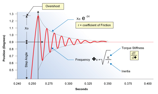
The equation above dictates where the resonance will shift towards. If you increase the numerator, K, the frequency location will increase to a higher speed. If you increase the denominator, J (the inertia), you will shift the speeds to a lower value.
Ramping quickly through the low speeds can solve many low speed resonance problems. Set your driver/controller acceleration to a higher value.
Since step motors rotate by a switching sequence in current from phase to phase, at slow speeds, each pulse that is sent to the motor must rise and deplete (also known as a current-rise time). At slow speeds, each step it takes should have plenty of time to fully rise to 100% current and deplete. You will receive maximum power and thus, the reason why torque-speed curves have high torque at the low speeds.
As you increase your speed, there is not enough time per step for the current to completely rise and deplete. At higher speeds, you may only be receive 50% of the max allowable current.
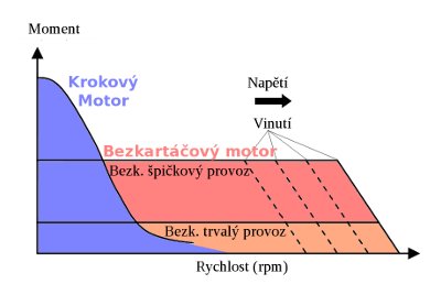
Voltage acts like a means to allow current to flow faster or slower. If you increase voltage, you are pushing the current through the motor windings at a faster rate. Now, instead of only rising and depleting about 50% of the max current, perhaps it has increased to about 60 or 75% by increasing the voltage.
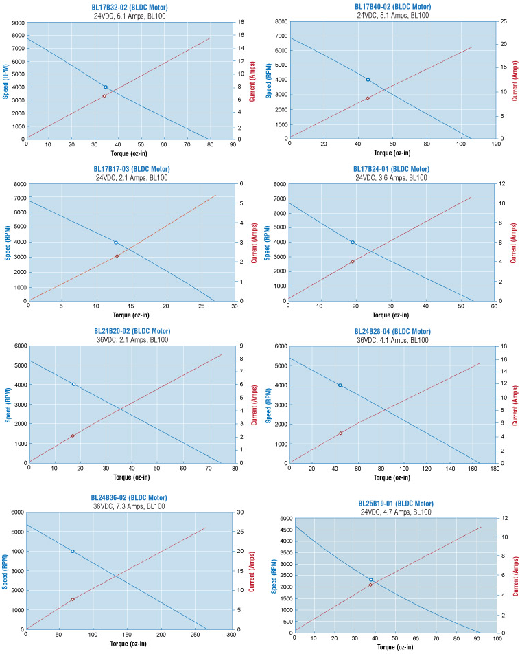
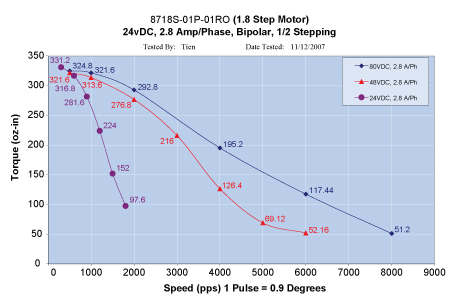
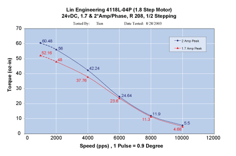
Below shows a few curves that prove what different voltages and currents do to the torque-speed curves of several motors.
Bipolar and Unipolar Operation
Lin Engineering step motors are available with either 2-coil Bipolar, or 4-coil Unipolar windings. Bipolar motors have 4 leads, while unipolar motors have 6 leads. Additionally, some motors are designed with 8 leads, so they may be connected in a variety of ways.
Connection Instructions
By following a series of easy steps, the below charts can be used to properly connect your motor to your drive.
1. Determine how many lead wires your motor has 4, 6, or 8 wires. Locate the proper box below.
2. Next, examine the color code of the lead wires on your motor; find the row of colors that match your wires, this is your “color code”. You will have either Code 1, Code 2, or Code 3. For example, if you have 4 wires and the wires are Red, Blue, Green, Black, your color code is 1.
3. Next, connect the proper color to the appropriate terminal on your drive. If you have a Bipolar drive, the terminal on your drive will be labeled A, A-, B, B-.
For example, if using the above 4 wire motor with color code 1, the Red wire would be connected to A, Blue connected to A, Green connected to B, and Black connected to B.
If you have a Unipolar drive, the terminal will be labeled A, B, C, D and A/C Common, B/D Common (or comm)
| Color Code 1 | Red | Blue | Green | Black |
| Color Code 2 | Brown | Orange | Red | Yellow |
| Color Code 3 | Red | Red/White | Green | Green/White |
| Bipolar Driver | A | A- | B | B- |