Controller allow full motor and communication over standard industrial bus.
Most used is communication over USB, Ethernet, RS485. New options are CanBus and EtherCat.
Controller are :
stand alone units, integrated power stage (driver) and control unit ( CPU+Mem )
no need for PLC, controller can be programmed by PC and than work completely stand alone
can communicate over industrial bus RS232/RS485/CanBus/EtherNet/EtherCat
Drivers for Stepper Motors:
Drivery are simple power stages - they need external control unit (PLC),
that is sending TTL signal 0 to 5Volts to driver inputs STEP/DIR. Driver is amplifing this signal
to selected current levels (selected at driver). Driver limits the current and keeps motor in safe
zone (so motor winding can not burn). Drivers also enable Microstepping. That make motion of stepper
motor even more precize (up to 256 divisions per one step).
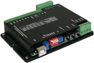
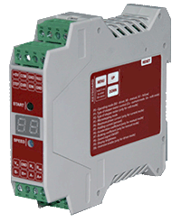
Stepper Motor Control over standard Ethernet LAN by standard TCP/IP protocol
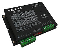
24-48VDC / Max 4,2 Amper (New version 8,0 Ampers)
Microstepping 1/128
Remote control through Ethernet
Standalone motor control according to one of 4 independent executing program sequences, stored in the controller’s memory
Real time stepper motor control by commands forwarded from a computer via USB or through a local network Ethernet
Recording and reading of executing program sequences through a local network Ethernet or USB interface
The controller keeps in memory up to 4 independent executing program sequences. Each one can be started in a standalone control mode or called via communication interface (Ethernet or USB); every program can be called and used as a subprogram of any other program. Every program contains up to 255 control commands
Program control of an internal relay is provided
Motor control parameters (such as current per phase, holding current, microstepping mode, control mode) are adjusted using menu of the controller or via communication interface (Ethernet or USB)
Pulse position control with standard signals 0/5 VDC (up to 24 VDC on condition that additional current limiting resistances are used) «STEP», «DIR» and «ENABLE» is provided
Analog speed control is provided: using internal or external potentiometers or analog voltage signal 0..5 VDC
Analog position control is provided: using internal or external potentiometers or analog voltage signal 0..5 VDC
Motor stop is provided as received signal from an emergency sensor
Change of motor motion direction is provided as received signal from a revers sensor
Homing position function is provided
Storage of a mark (current) position and motion to the mark position is provided
Synchronized operation of several controllers and other devices is provided by inputs and outputs
Automatic source voltage control – if the power supply falls outside the allowance range (less than 20 VDC or more than 51 VDC) when the controller is switched on or within 2 seconds during operation, the controller outputs the alarm
A motor acceleration and deceleration is adjusted from a controller menu or via communication interface
The controller is equipped with an internal brake resistor. External brake resistor can be connected as well if needed
Alarm sound and indication of a code of the alarm are provided
2-sign 7-segment display is provided for indication of alarms, control modes and the controller adjustment
32-bit password secures access through the local network, 1 second interval of authorization provides strong access protection (exhaustive search requires 136 years)
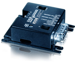
Bipolar Stepper Motor Driver
12-24VDC; 0.35-2.0A; 1/256 Microstepping
STEP/DIR input opticaly isolated
Optional Power Reduction 33%
Low Power Loss
Effective Current Control
Termal Protection, Under Voltage Protection
Inducation of ON state
Sinusouidal Current Form
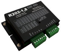
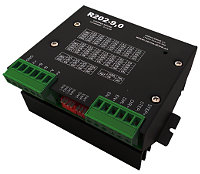
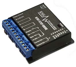
Bipolar Stepper Motor Driver
Input Voltage 24 to 80 V =
Phase Current 0.3-2.0Amps or 2-7A
10x microstepping
Optional Power Reduction 33%
Low Power Loss
Effective Current Control
Termal Protection, Under Voltage Protection
Inducation of ON state
Sinusouidal Current Form


 Controller R272-42-ETH
 Software SMC for Ethernet LAN Controllers
 Request Quote

 Lab View and Visual Basics Examples
 Software for R256 - Stepper Motor Controll


 Dimensions